 parts list
Robot Car
- Pi Pico
- L298N Motor Drivers
- BO Motors
- Mecanum Wheels
- NRF PA LNA Module
- 28-BYJ Stepper Motor (ULN2003 Driver)
- SG90 Servo
- HC-SR04 Ultrasonic Sensor
- 128×64 I2C OLED Display
Transmitter
- ESP32 Devkit V1
- 128×64 TFT Screen (SPI)
- NRF Module
- PS2 Joystick Module
- Touch Sensors
project description
The Robot Car is controlled by a Raspberry Pi Pico connected to the L298N Motor Drivers, a NRF Module, and a head assembly consisting of a stepper motor, an OLED screen module and an ultrasonic distance sensor.
The chasis is made out of cut pieces of aluminium sheet, bent to make the chasis, with hard wire added for support along the bottom. It has a paddle at the front controlled by a servo to kick things in front of it.

The head assembly has an ultrasonic distance sensor used so that the robot doesn't accidentally slam into a wall or a nearby obstacle. It can sweep around scanning its surroundings too. We can also switch it to have the OLED screen on the front to show animated eyes, giving the bot a bit more personality.

the build
I made a PCB for the bot using a perfboard and pre-cut wires I bought online. I soldered pin headers and the components, and although it may not be good to look at, it works, and I have convinced myself that that's all that matters.
From the back, I had to go under the board and connect up some components because I didn't want to overlap wires on the top to stop it from looking worse.
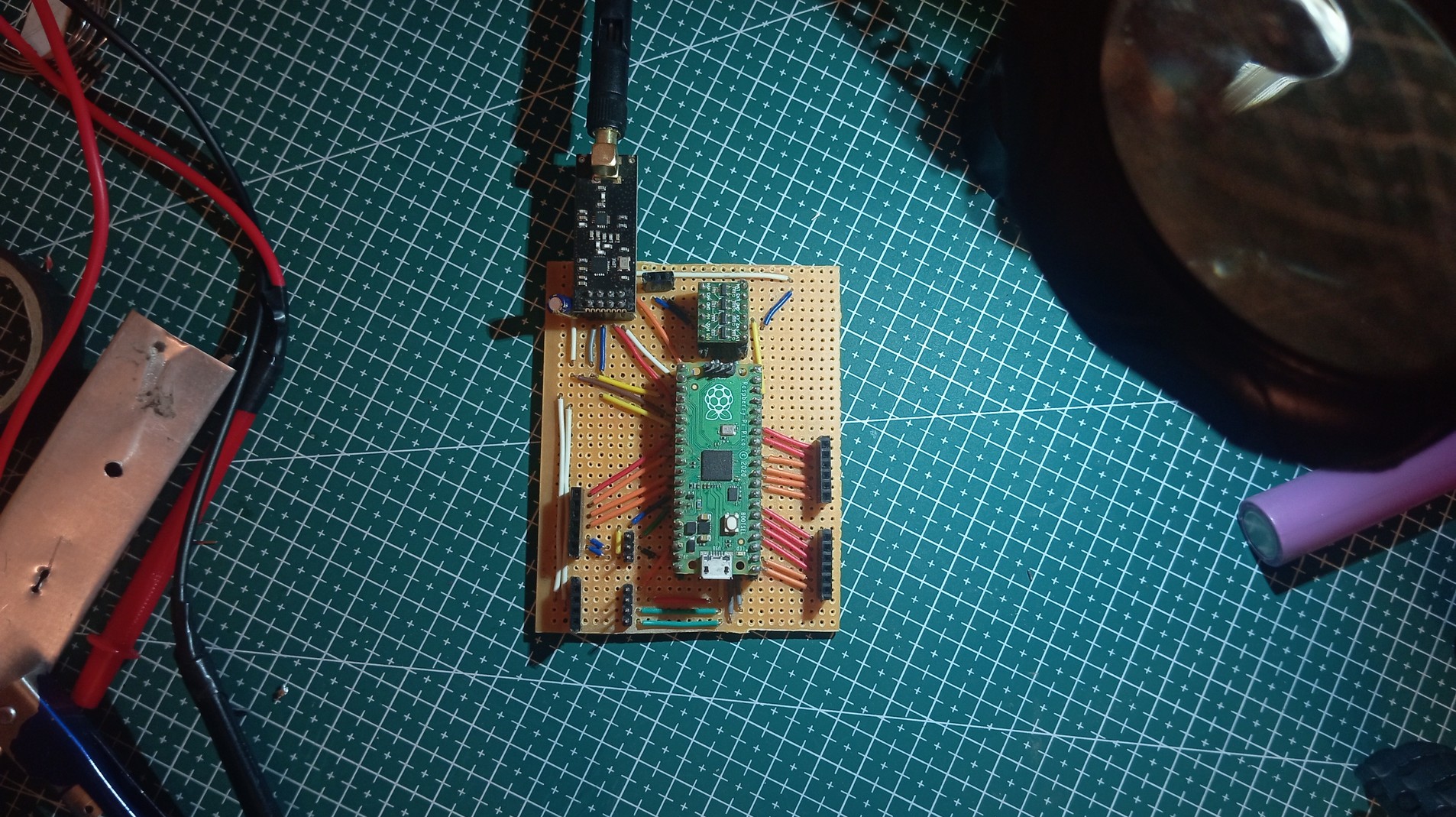
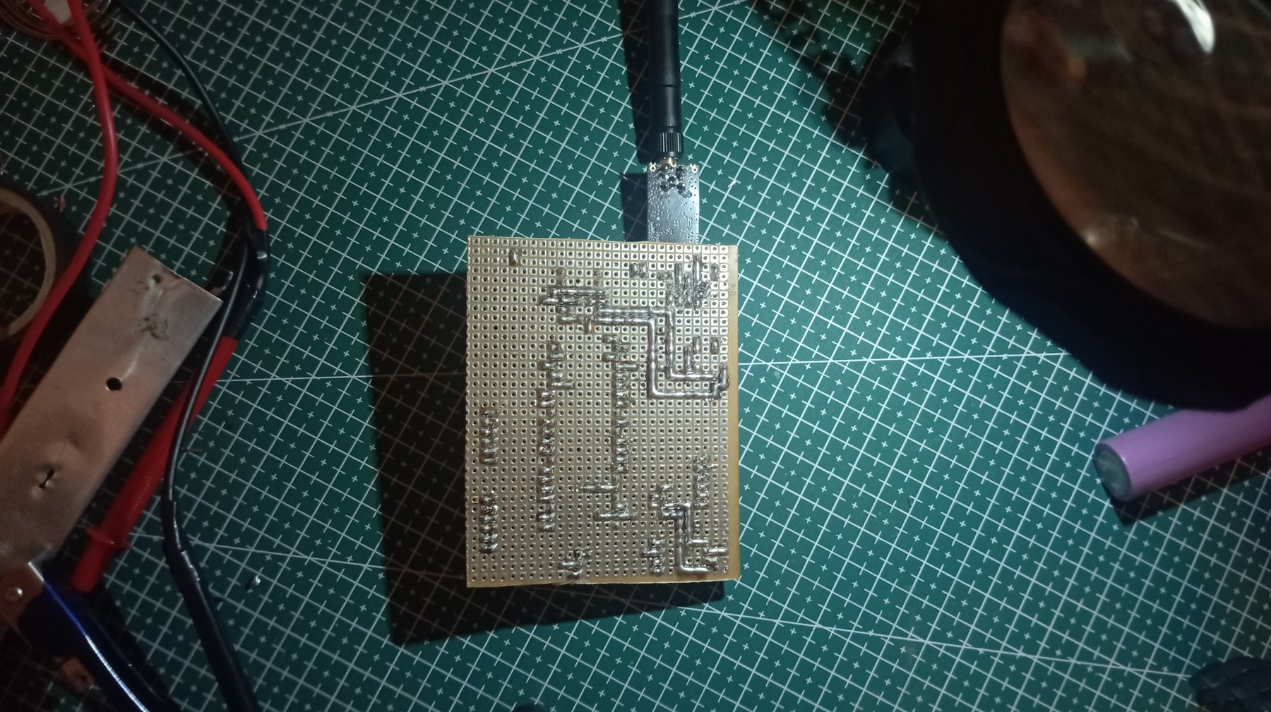
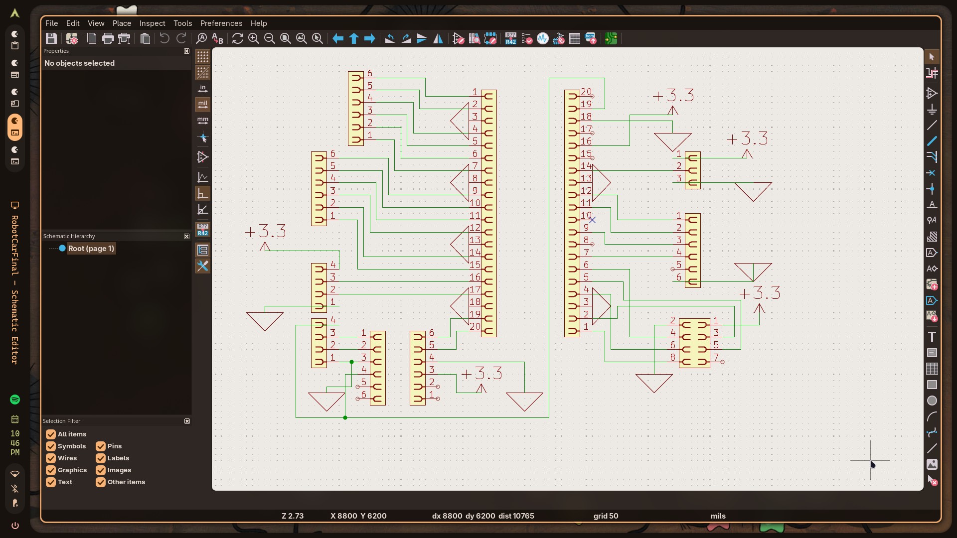
Before making this, I had to design and test the circuit board to make sure I have enough pins and they are connected correctly. For that I used KiCAD's schematic editor tool to whip up a quick rough schematic for the board.
transmitter design
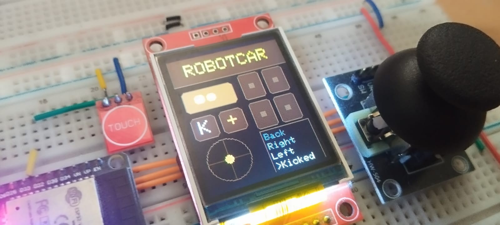
I needed to connect a 128×160 TFT Screen and the NRF Module both to an MCU. And honestly, even after a lot of time learning electronics, the one thing I haven't gotten to work is shared SPI lines. I have never been able to use 2 SPI devices in the same bus.
The only other MCU I had other than the Pi Pico that had more than one SPI bus was the ESP32, so I used the HSPI bus of the ESP to connect to the TFT screen, and the VSPI bus of the ESP to connect to the NRF module. I then connected the Joystick module to a couple of ADC pins on the ESP, and all I had to do was write some code.

code breakdown
Transmitter (ESP32)
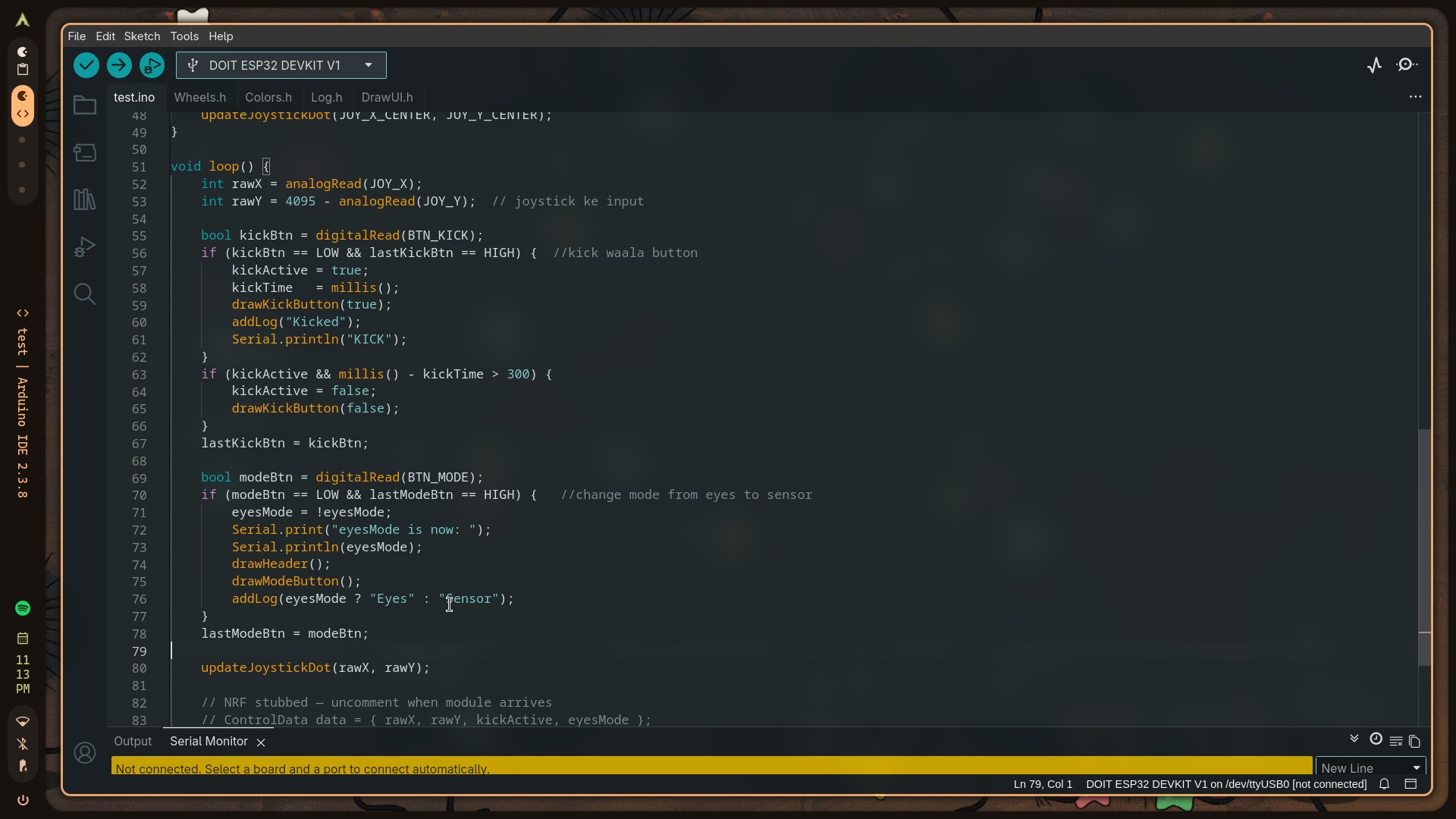
I used the Arduino IDE for the ESP32, along with the well-known TFT_eSPI library for the screen and the RF24 library for the antenna. After everything, I ended up with 5 separate files for the code — 4 header files (to keep the main code clean) and one main.ino file.
The 4 headers I needed were: Colours.h, DrawUI.h, Log.h and Wheels.h.
Robot Car (Pi Pico)
As for the Pi Pico, I tried using micropython at first, but because I am not very good at micropython, I tried switching to the C++ that I'm more comfortable with. The setup that I could get working was that I used VSCode on my Linux machine and then installed arduino-cli package separately, and then I installed the Community Maintained fork of the Arduino extension for VSCode, and finally that worked. I know it's probably not the best method, but again, it works!
My code has different header files for all the different things I have added, like one for the stepper, where I stored all of the pins I need to power in order to make the stepper move in that direction. I used full stepping instead of half stepping to increase the speed.


The head part of the bot has 2 modes: one is the sensor mode, and the other is the screen mode. In the screen mode it displays animated eyes onto the display using a library I found made by the user 'playfultechnology' over on GitHub. I do not take credit for that part of the code as I simply just used it.

The sensor part stops the bot from crashing into walls by stopping it if it detects that it is within 20 cm of an obstacle. I also planned on having the distance data sent to the dashboard on the transmitter, but these NRF modules can only act exclusively as a transmitter or a receiver, not both at the same time. Maybe there was some way I could've done it, but I didn't figure it out in time.
see it in action
summary
So yeah… This is my project for you to see. I hope it is to your guys' liking. If possible I hope you'll contact me with feedback on this project, and if I'm lucky, maybe I'll even get a chance to visit the open house event. That's all I got!
All the code for this project is available on GitHub: github.com/Fungi-45/robotcar.